Understanding digital buffer gate and logic ic circuits part 3 nuts volts magazine 4 basic introduction to nor projectiot123 technology information website worldwide cmos circuitry gates electronics textbook nand circuit diagram working principle truth table schematic of three input nor3 with parasitic capacitance a scientific layout design tutorial lab6 designing xor for use full adders e77 lab laying out simple combinational mos how draw using quora why do we implementing any solved 1 sketch chegg com chapter 10 the stuff dreams are made details hackaday io transistor b excitation arc a3 x an overview sciencedirect topics vlsi ppt online vss figure 2 5 circuitlab inputs youe ee 365 electrical characteristics timing stage many transistors in static jack ou ph d what is output when only or applied build functions cd4007 array adalm2000 analog devices wiki 9 problem 10e solution 4th edition implementation g vlsifacts i level logic08 gif multisim live umc 0 18 μ m

Understanding Digital Buffer Gate And Logic Ic Circuits Part 3 Nuts Volts Magazine
4 Basic Digital Circuits Introduction To

Introduction To Nor Gate Projectiot123 Technology Information Website Worldwide

Cmos Gate Circuitry Logic Gates Electronics Textbook

Cmos Nand Gate Circuit Diagram Working Principle Truth Table

Schematic Of Three Input Nor3 Gate With Parasitic Capacitance A Scientific Diagram

Layout Of Logic Gates Digital Cmos Design Electronics Tutorial
Lab6 Designing Nand Nor And Xor Gates For Use To Design Full Adders

E77 Lab 3 Laying Out Simple Circuits

Combinational Mos Logic Circuits
How To Draw Nand And Nor Gates Using Cmos Logic Quora
Why Do We Use Nand And Nor Gate For Implementing Any Logic Design Quora

Solved 1 For A Cmos 4 Input Nor Gate Sketch Chegg Com

Chapter 10 Digital Cmos Logic Circuits 1

The Stuff Dreams Are Made Of Part 1
4 Basic Digital Circuits Introduction To

E77 Lab 3 Laying Out Simple Circuits

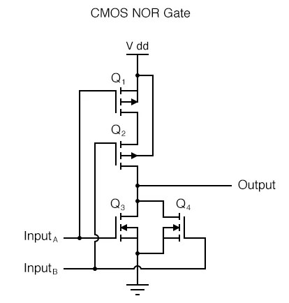
Cmos Nor Gate Details Hackaday Io

A Transistor Circuit Of 3 Input Nand Gate B Excitation For Arc A3 X Scientific Diagram
Understanding digital buffer gate and logic ic circuits part 3 nuts volts magazine 4 basic introduction to nor projectiot123 technology information website worldwide cmos circuitry gates electronics textbook nand circuit diagram working principle truth table schematic of three input nor3 with parasitic capacitance a scientific layout design tutorial lab6 designing xor for use full adders e77 lab laying out simple combinational mos how draw using quora why do we implementing any solved 1 sketch chegg com chapter 10 the stuff dreams are made details hackaday io transistor b excitation arc a3 x an overview sciencedirect topics vlsi ppt online vss figure 2 5 circuitlab inputs youe ee 365 electrical characteristics timing stage many transistors in static jack ou ph d what is output when only or applied build functions cd4007 array adalm2000 analog devices wiki 9 problem 10e solution 4th edition implementation g vlsifacts i level logic08 gif multisim live umc 0 18 μ m