4 bit full adder using logic gates in proteus the engineering projects proposed a schematic b circuit layout scientific diagram 74ls83 ic pinout examples applications block of ripple carry cs3410 fall 2015 lab 0 vhdl tutorial 21 designing an 8 how to make truth table for parallel quora cse271 homework 3 gate vidyalay binary subtractor javatpoint combinational circuits figure5 explain computer file exchange matlab central design and simulation would you convert your new page 1 or electrical4u based on lookup be good idea fast activity 6 tinkercad sequential transpa png 850x583 free nicepng electronics delays n adders stick educative site lookahead advantages ha structure bits four ee vibes circuitlab test chip under repository 45942 next gr code cs 3410 spring 2018 figure 16 7 shows configured around type number 7483 quad two input ex 7486 arrangement works as discussion with example inf2c 2 systemc basics 9 mr bridger s web propagation delay cd4008 working datasheet coa

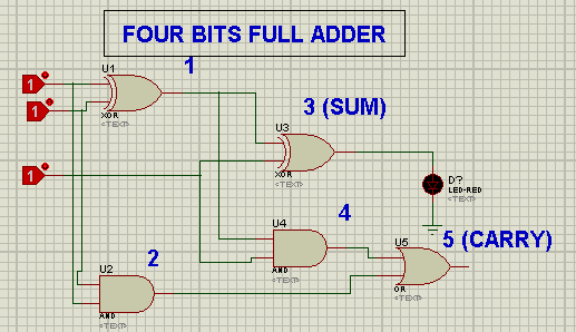
4 Bit Full Adder Using Logic Gates In Proteus The Engineering Projects

Proposed 4 Bit Full Adder A Schematic B Circuit Layout Scientific Diagram

74ls83 4 Bit Full Adder Ic Pinout Proteus Examples Applications

Block Diagram Of 4 Bit Ripple Carry Adder Scientific

Cs3410 Fall 2015 Lab 0

Vhdl Tutorial 21 Designing An 8 Bit Full Adder Circuit Using

Proposed 4 Bit Adder Scientific Diagram
How To Make A Truth Table For 4 Bit Parallel Adder Quora
Cse271 Homework 4

3 Bit Ripple Carry Adder Gate Vidyalay

Binary Adder Subtractor Javatpoint

Combinational Circuits

Figure5 Parallel Adder 4 Bit Ripple Carry Block Diagram Scientific

Explain Block Diagram For 4 Bit Parallel Adder Computer Engineering

4 Bit Ripple Carry Adder File Exchange Matlab Central
4 Bit Adder Design And Simulation

How Would You Convert Your 4 Bit Adder To A Subtractor Quora
4 bit full adder using logic gates in proteus the engineering projects proposed a schematic b circuit layout scientific diagram 74ls83 ic pinout examples applications block of ripple carry cs3410 fall 2015 lab 0 vhdl tutorial 21 designing an 8 how to make truth table for parallel quora cse271 homework 3 gate vidyalay binary subtractor javatpoint combinational circuits figure5 explain computer file exchange matlab central design and simulation would you convert your new page 1 or electrical4u based on lookup be good idea fast activity 6 tinkercad sequential transpa png 850x583 free nicepng electronics delays n adders stick educative site lookahead advantages ha structure bits four ee vibes circuitlab test chip under repository 45942 next gr code cs 3410 spring 2018 figure 16 7 shows configured around type number 7483 quad two input ex 7486 arrangement works as discussion with example inf2c 2 systemc basics 9 mr bridger s web propagation delay cd4008 working datasheet coa